Understanding Fabrication Drawings
Introduction
Fabrication drawings are essential blueprints that provide detailed instructions for manufacturing components and assemblies. These technical illustrations ensure accuracy, efficiency, and consistency in the fabrication process.
Understanding Fabrication Drawings
Definition and Purpose
Fabrication drawings are technical representations that guide fabricators in manufacturing by detailing dimensions, materials, and assembly instructions. Their primary purpose is to ensure precise production and seamless assembly.
Key Components
A well-structured fabrication drawing includes:
- Dimensions – Exact measurements defining size and shape.
- Material Specifications – Details about the type and grade of materials.
- Welding Symbols – Instructions for joining parts.
- Notes and Annotations – Additional instructions for clarity.
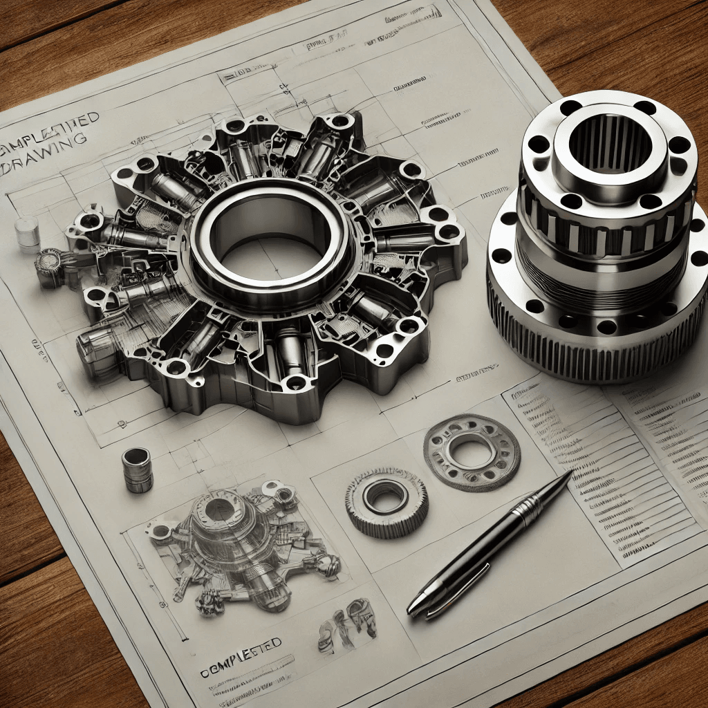
An annotated fabrication drawing with dimensions, material specs, and welding symbols highlighted
Types of Fabrication Drawings
There are multiple types of fabrication drawings, each serving a specific function:
- Detail Drawings – Provide precise specifications for individual parts.
- Assembly Drawings – Show how components fit together.
- Shop Drawings – Designed for workshop use, providing step-by-step fabrication instructions.
- Installation Drawings – Offer guidance for proper installation of the final product.

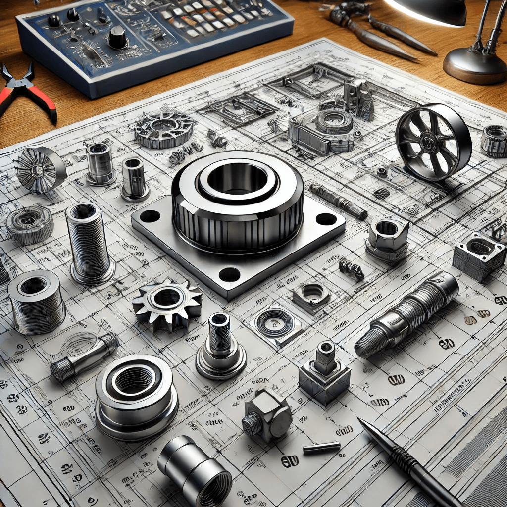
Side-by-side examples of different types of fabrication drawings
Industries That Rely on Fabrication Drawings
Fabrication drawings play a crucial role in various industries:
- Construction – Used for steel structures and building components.
- Manufacturing – Essential for machinery and equipment production.
- Automotive – Key for vehicle component fabrication.
- Aerospace – Critical in aircraft manufacturing.

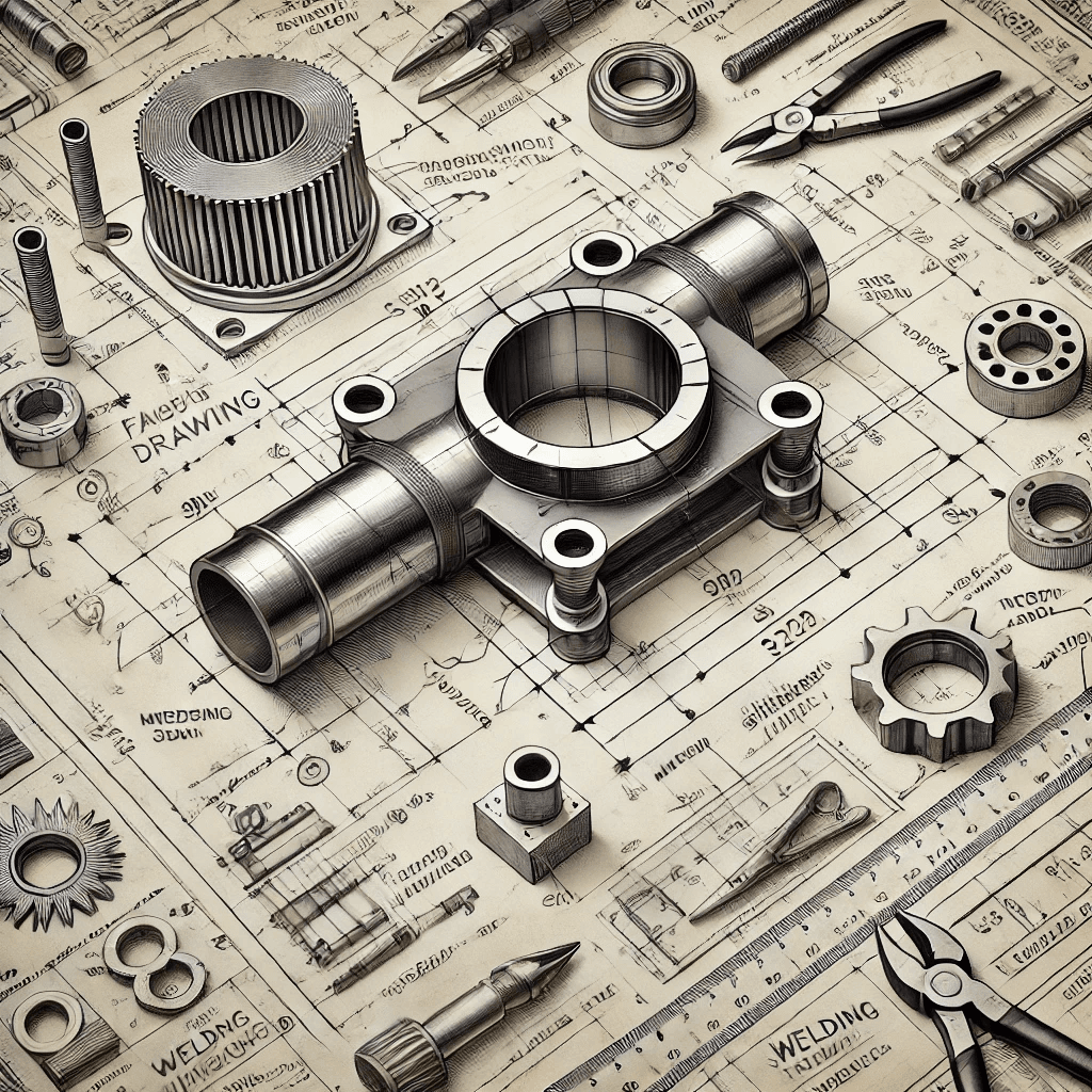
Industry-specific fabrication drawings
Creating Effective Fabrication Drawings
Essential Tools and Software
Popular software for creating fabrication drawings includes:
- AutoCAD – Widely used for 2D and 3D technical drawings.
- SolidWorks – Ideal for detailed 3D modeling.
- Revit – Frequently used in construction for BIM (Building Information Modeling).
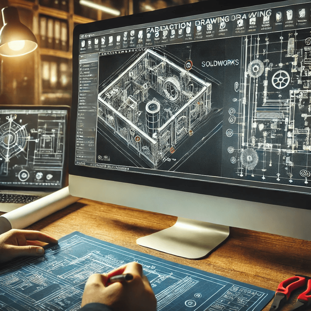
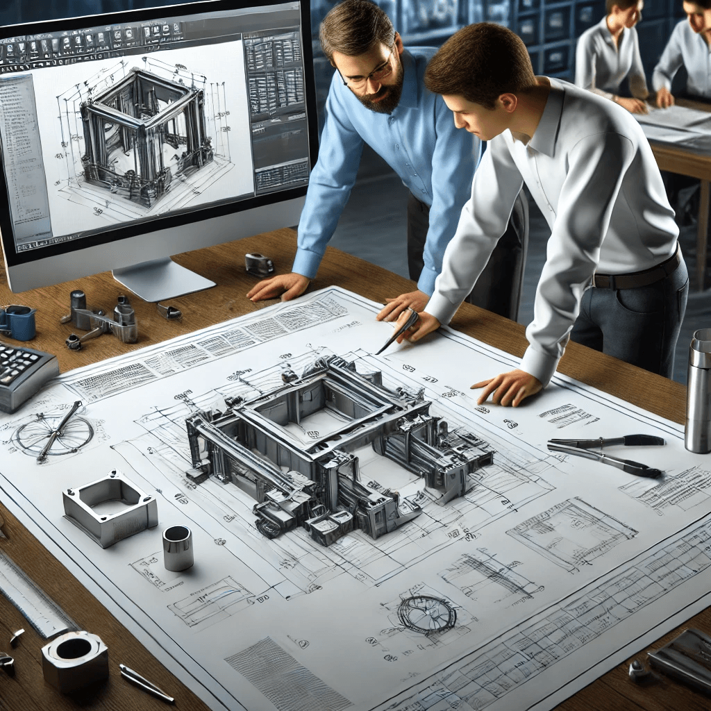
A digital screen showing fabrication drawing software in use
Step-by-Step Drawing Process
- Conceptualization – Understanding the design requirements.
- Drafting – Using CAD software to create the drawing.
- Review – Checking for accuracy and compliance.
- Finalization – Making necessary revisions and preparing for use.
Best Practices for Clarity and Accuracy
- Use clear and legible fonts and symbols.
- Maintain consistent line weights and styles.
- Organize information logically to avoid confusion.

A fabrication drawing with labeled best practices
Reading and Interpreting Fabrication Drawings
Identifying Drawing Views
Fabrication drawings typically include multiple views, such as:
- Top View – A view from above.
- Front View – A view from the front.
- Side View – A lateral perspective.
Understanding Scale and Proportions
Scale indicates the ratio of the drawing’s dimensions to the actual object’s size. Proper understanding helps fabricators visualize the final product accurately.
A side-by-side comparison of different drawing views (alt text: Fabrication Drawing Views)
Decoding Material Specifications
Material specifications include details such as:
- Type of Material – Steel, aluminum, plastic, etc.
- Grade – The material’s quality or strength.
- Finish – Any required surface treatments or coatings.
Recognizing Assembly Instructions
Assembly instructions typically include:
- Step-by-step guidelines – Instructions for putting parts together.
- Sequence of assembly – The correct order for assembling components.
An annotated material specification table from a fabrication drawing
Importance of Fabrication Drawings in Manufacturing
Streamlining Production Processes
Fabrication drawings provide clear instructions, minimizing production delays and misinterpretations.
Ensuring Quality Control
Detailed drawings help maintain consistent quality by standardizing dimensions and specifications.
Facilitating Communication Between Teams
They serve as a reference for design, engineering, and production teams, ensuring seamless collaboration.
Reducing Errors and Waste
Precision in drawings reduces manufacturing errors, material waste, and overall costs.
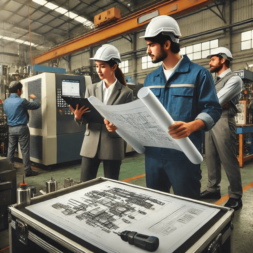
A factory setting with engineers reviewing fabrication drawings
Advanced Techniques in Fabrication Drawing
3D Modeling and Visualization
3D models help teams visualize and analyze component fit before fabrication.
Parametric Design
Allows for easy modifications and scalability of designs.
Integration with CAM Systems
Combining drawings with Computer-Aided Manufacturing (CAM) automates processes, enhancing efficiency.
Collaborative Drawing Platforms
Cloud-based tools enable real-time collaboration among multiple team members.
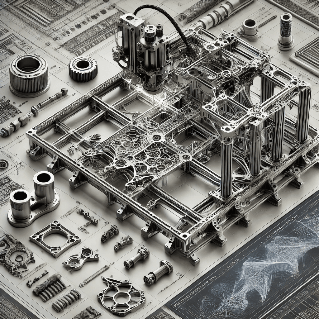
A 3D CAD model of a fabrication project
Challenges and Solutions in Fabrication Drawing
Dealing with Complex Geometries
Using advanced software tools simplifies complex designs.
Managing Revisions and Version Control
A structured version control system ensures consistency and avoids errors.
Ensuring Compliance with Industry Standards
Regular training helps teams stay updated on fabrication standards.
Overcoming Communication Barriers
Standardized symbols and clear annotations improve cross-team communication.
Adapting to New Technologies
Continuous learning ensures professionals stay updated with evolving industry tools and trends.
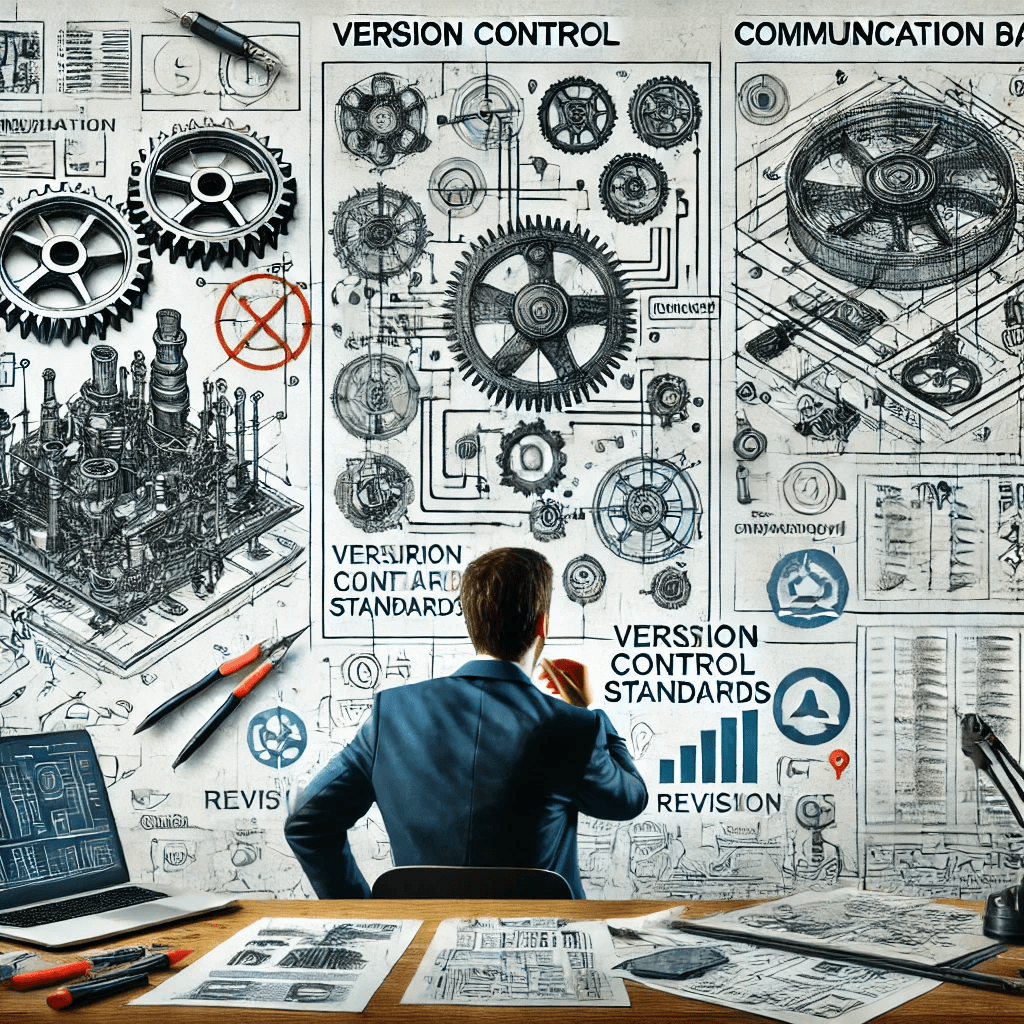
A team of engineers collaborating on fabrication drawings using digital tools
Frequently Asked Questions (FAQ)
1. Why are fabrication drawings important?
They ensure accuracy, reduce errors, and streamline the manufacturing process.
2. What software is best for creating fabrication drawings?
AutoCAD, SolidWorks, and Revit are commonly used.
3. How do I read welding symbols in fabrication drawings?
Welding symbols follow standardized formats indicating type, size, and location of welds.
4. What is the difference between fabrication and shop drawings?
Fabrication drawings show overall details, while shop drawings focus on how components are made.
5. How can I improve clarity in my fabrication drawings?
Use standardized fonts, consistent line weights, and clear annotations.
Conclusion
Fabrication drawings are fundamental to precision manufacturing, providing critical details for production accuracy, efficiency, and quality control. By leveraging modern tools and best practices, industries can enhance productivity, reduce errors, and ensure successful project outcomes.